How to cut the model using Clipping Planes Featured
This question has been asked a couple of times, so here is how to do it.
-
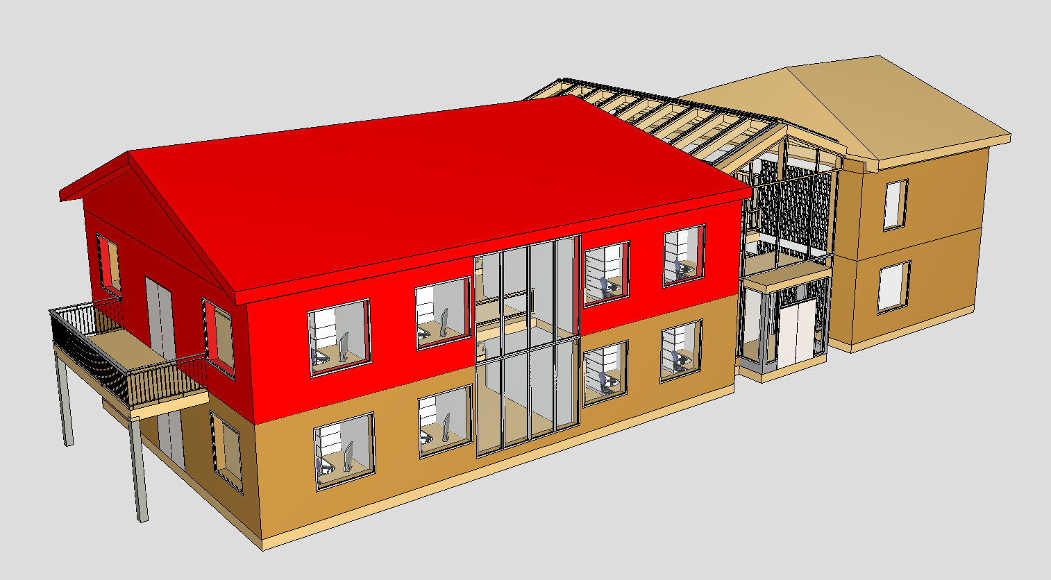
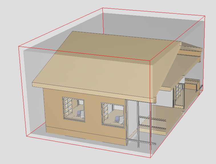
First, we need to select some objects to create clipping planes based on the bounding box of the selection. Here is my selection.
-
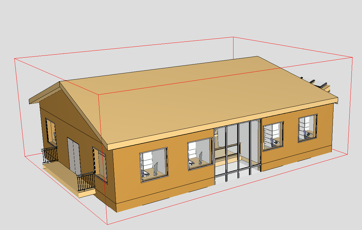
Next, I will create the clipping planes based on this object selection.
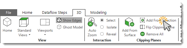
This will create six clipping planes in a box-like formation.
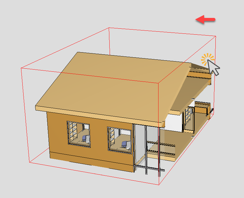
If I need to tweak the clipping planes, I can hold the Shift key and drag the faces.
-
The next step is to create a Location Prism using those clipping planes.
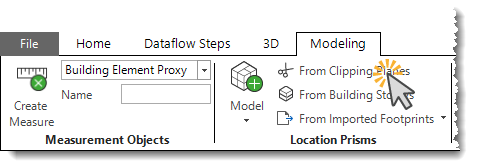
This function creates a Location Prism that we can use to split the model.
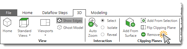
Before that, I will remove the clipping planes since they are no longer needed.
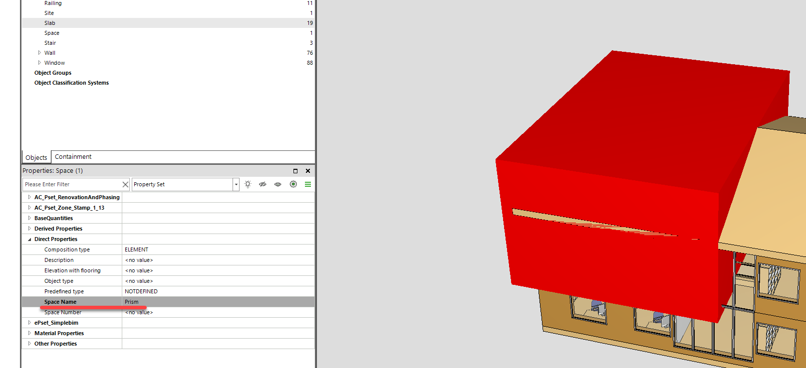
Then, I will give a name to the Location Prism.
-
For this, we just need one Dataflow step: ‘Add Location Using Prisms (Optional Split)’. So let’s configure that.
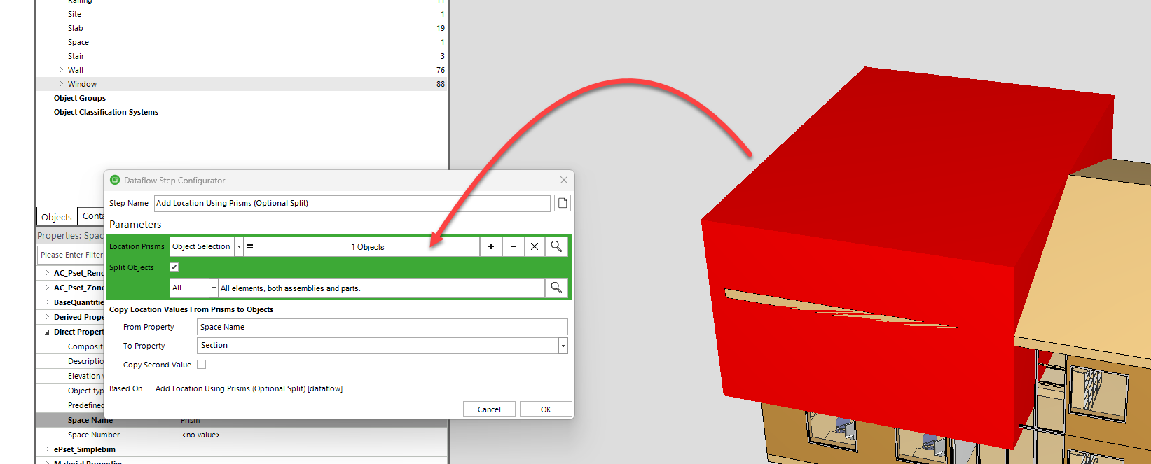
I drag and drop the Location Prism into the configuration to be used as the Location Prism (or cutting object in this context). I choose to split all the objects, and then I copy the ‘Space name’ to the ‘Section’ property, which is applied to all the objects inside the Location Prism. After we have configured this step, we can simply run it..
-
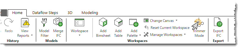
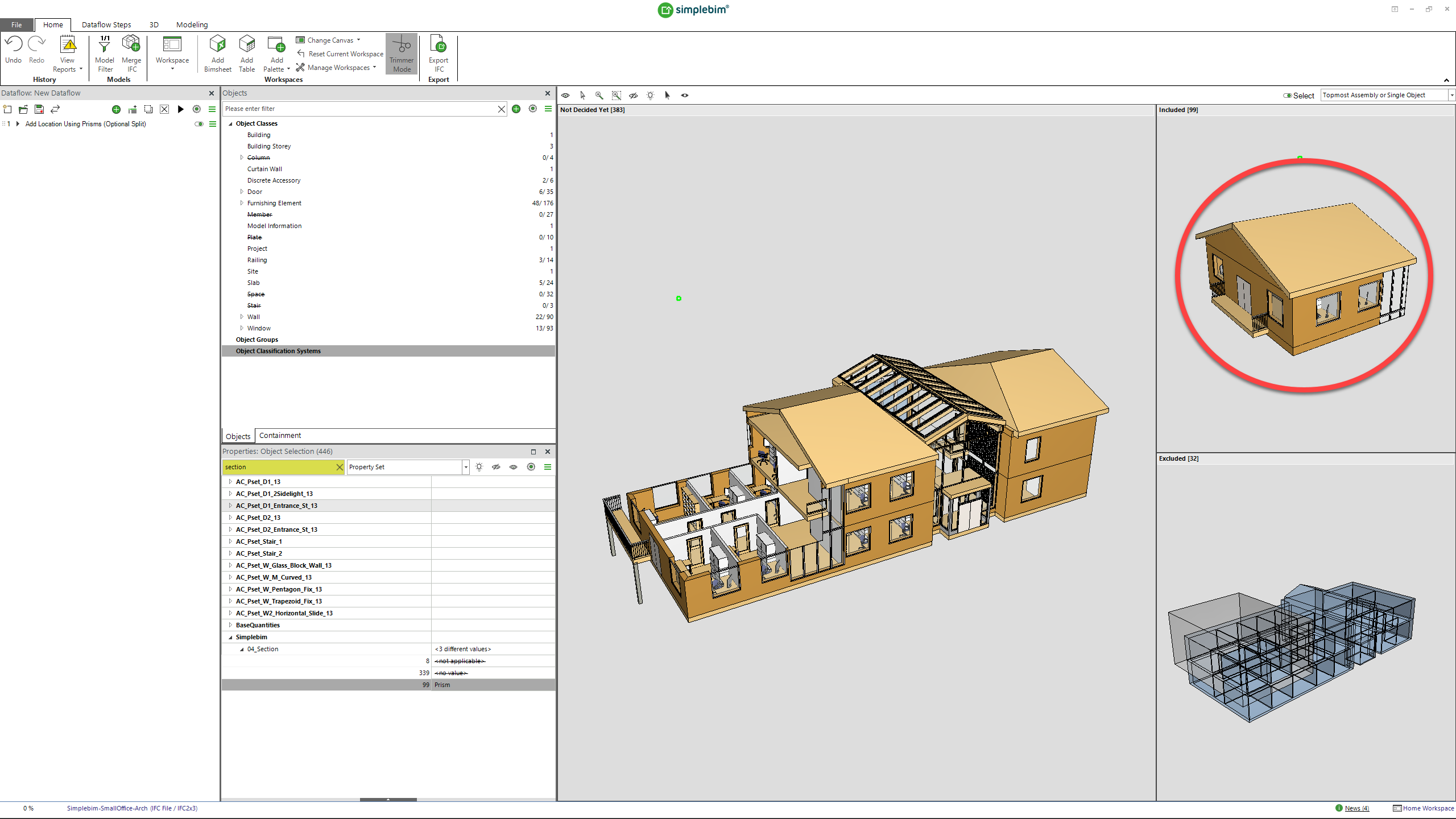
As a final step, I want to export all the objects that were cut and are inside the Location Prism. For that, I can turn on ‘Trimmer Mode’ and select all the objects.
After that, I can select all the objects that have ‘Prism’ as their ‘04_Section’ property value and drag them into the ‘Included’ bucket.
-
Now, when I export the model, only the objects that are in the ‘Included’ bucket will be exported as an IFC file.
Comments
5 comments
This is great! I think we should improve the workflow further by asking for the name of the location prism always when we are creating location prisms from clipping planes. Currently it is a bit too easy to forget to give the location prism a name…
Hello Gio, thank you.
I have a question related to the prism I generated this way. How can I edit it? Is it also possible to make some changes to it? As you can see here, I have two prisms, and I think they have a small overlap. I would like to correct this.
Another question I have is: how can I generate two prisms based on this red line? Is there any way to do this using clipping planes?
Hi!
To get rid of the overlap, you can subtract one prism from another using Boolean operations in the Geometry Editing section of the “Modeling” tab.
The easiest way is probably to draw a polygonal horizontal footprint for the location prism instead of using the clipping planes. 🤔
To make the drawing as easy as possible, you can switch to the top view by pressing the “1” key on your keyboard and set the projection mode of the 3D window to “Orthogonal” in the 3D Options.
I love it – this was exactly what I needed to discuss with a client, and we went through the method step by step!
Please sign in to leave a comment.